Front Lower Control Arm Bushing Replacement (4WD)
Replacing the front and rear bushings in the lower control arm on a 4WD L300 / Delica Star Wagon, converted from the factory service manual.
- Manual section
- Group 33 — Front Suspension
- Manual pages
- 33-26 to 33-27-1 (4WD)
- Applies to
- L300 / Delica Star Wagon, 4WD. Front bushing procedure differs by build date — vehicles built up to Sept 1988 vs from Oct 1988.
Tools needed
MB991183
bushing remover/press (front)
MB990883
bushing remover/press (front and rear)
MB991182
front bushing tool
MB991180
bushing tool, used across both front and rear jobs
MB991318, MB991320, MB991319
front bushing pull-out/press-in set (vehicles built Oct 1988 onward)
MB991152
front bushing ring removal (Oct 1988 onward)
MB991181
rear bushing press tool
Before you start
Getting the lower control arm off the vehicle is the ball joint replacement job’s lower-arm removal procedure — the same clearance issue applies (disconnect the sway bar from the lower control arm first). This guide picks up once the arm is off the vehicle and on the bench.
Front bushing — vehicles built up to September 1988
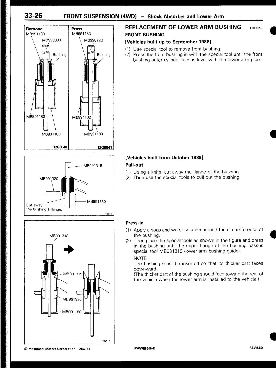 Factory service manual (PWWE8608), page 33-26.
- Use the special tool (MB991183 / MB990883) to remove the front bushing.
- Press the new front bushing in with the special tool until the bushing’s outer cylinder face sits level with the lower arm pipe.
Front bushing — vehicles built from October 1988
Different technique — the bushing has a flange that needs cutting away first, then it’s pulled rather than pressed straight out.
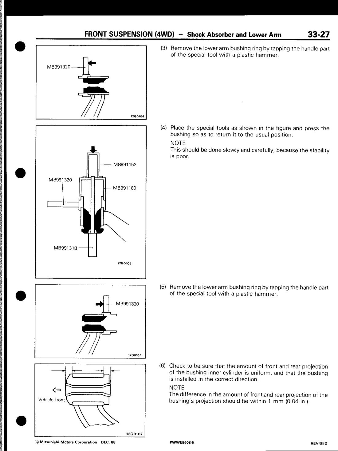 Factory service manual (PWWE8608), page 33-27 — steps 3–6, press-in and bushing-ring removal.
Pull-out:
- Using a knife, cut away the flange of the bushing.
- Use the special tools (MB991318, MB991320, MB991180) to pull the bushing out.
Press-in:
- Apply a soap-and-water solution around the circumference of the new bushing — this is the lubricant for pressing it in, not a cleaning step.
- Place the special tools as shown in the manual and press the bushing in until the upper flange passes special tool MB991319 (the lower arm bushing guide).
- The bushing must go in with its thicker part facing downward. When the lower arm is installed on the vehicle, the thicker part of the bushing should face toward the rear.
- Remove the lower arm bushing ring by tapping the handle of the special tool with a plastic hammer.
- Reposition the special tools and press the bushing back to its usual position — do this slowly and carefully, the setup is described in the manual as “poor stability” at this stage.
- Remove the bushing ring again the same way (tap with a plastic hammer).
- Check the front/rear projection of the bushing’s inner cylinder is even, and that the bushing sits in the correct direction. The difference in projection front-to-rear must be within 1 mm.
Rear bushing
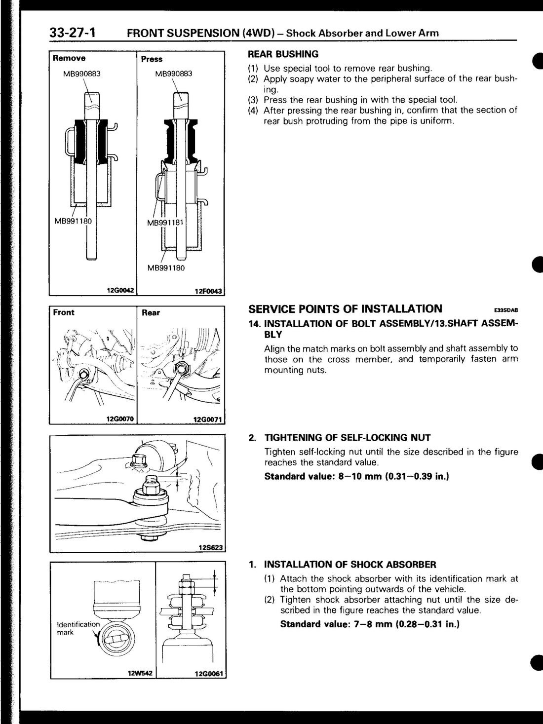 Factory service manual (PWWE8608), page 33-27-1.
- Use the special tool (MB990883) to remove the rear bushing.
- Apply a soap-and-water solution to the peripheral surface of the new rear bushing.
- Press the rear bushing in with the special tool (MB991181 / MB991180 / MB990883).
- After pressing it in, confirm the section of the bushing protruding from the pipe is uniform around the circumference.
Reinstalling the arm
Align the match marks you made on the bolt assembly and shaft assembly against the crossmember before final torque (see the ball joint guide’s torque table for lower arm-to-crossmember torque values — 90–120 Nm to the gear mounting crossmember, 90–110 Nm to the suspension crossmember).
Tighten the self-locking nut on the bolt assembly until the exposed bolt length reaches the standard value of 8–10 mm — this is a length check, not a torque spec, per the factory procedure.
Converted from the Mitsubishi factory service manual (document PWWE8608), Group 33 — Front Suspension, 4WD section, printed pages 33-26 to 33-27-1.
Last updated 2026-09-23.