Front Suspension Ball Joint Replacement (4WD)
How to replace the upper and lower front suspension ball joints on a 4WD Mitsubishi Delica / L300 Star Wagon, converted from the factory service manual — with torque specs, tools, and the full removal procedure.
Your progress on this job
0 / 10 must-do steps
Next up: Relieve torsion bar tension (wood block or back off adjusting nut)
- Manual section
- Group 33 — Front Suspension
- Manual pages
- 33-23 to 33-30 (4WD)
- Applies to
- L300 / Delica Star Wagon, 4WD, 1986–1994 (torque values revised Jun. 1994 — check your build date)
Tools needed
MB990809
pitman arm puller (breaks the ball joint taper off the knuckle)
MB990326
preload socket (ball joint starting torque)
MB990685 or MB990968
torque wrench
MB990635 or MB991113
steering linkage puller (tie rod ball joint)
MB990628
snap ring remover
MB991180 / MB991183 / MB990883
lower arm bushing remover/installer set (only needed if replacing bushings, not the joint)
⚠️ Safety first: the torsion bar will snap the upper arm upward if you skip this
The 4WD Delica’s upper control arm is under constant, heavy spring tension from the torsion bar — even with the van jacked up and the wheel off the ground. If you unbolt the upper ball joint without dealing with that tension first, the upper control arm can snap upward violently the instant the joint lets go. That can injure you and can damage the brake line running past it.
Before you unbolt anything:
- Wedge a solid block of wood (roughly 50 mm thick) into the gap between the upper control arm and the rubber bump stop underneath it, before you jack the van up. As the suspension droops under its own weight on the jack, it clamps down on the block and traps the spring energy safely.
- Alternatively (or in addition, if your torsion bars are cranked up for a lift), back off the torsion bar adjusting nut underneath the van to relieve load before attempting to pop the upper control arm.
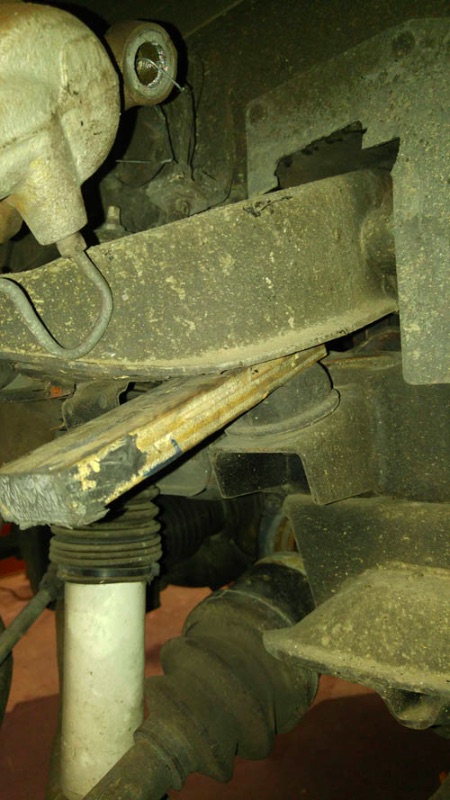 The wood-block safety trick in place, photographed during an actual R&R. Source: Delica Forum, “Lower Ball Joint Questions.”
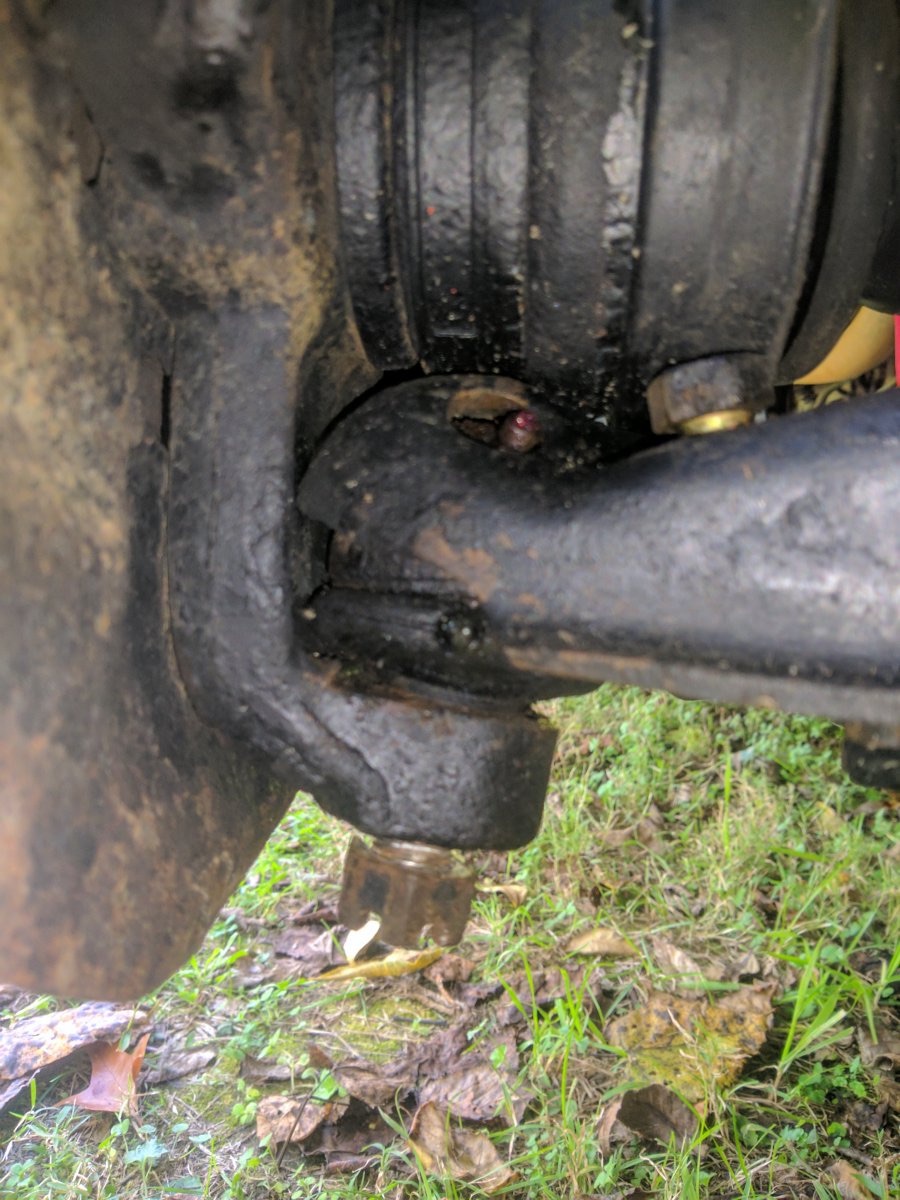 “Temp wooden spacer/shim at upper rebound bumper is only 1/2” thick. Maybe loosening torsion bar will allow more movement?” — Sputnik, Oct 19, 2020, Delica Forum.
This applies whether you’re doing the upper ball joint on its own or pulling the whole knuckle assembly as described below.
The one thing to know before you start
On this vehicle, the ball joints are not standalone, bolt-in parts. The upper ball joint is riveted to the upper arm, and the lower ball joint is integral to the lower arm. The factory manual’s “ball joint replacement” procedure is actually whole arm replacement — you remove the upper arm or lower arm as an assembly, then fit a new one. The only part that’s separately serviceable is the rubber dust cover (boot).
So “replace the ball joints” on a Delica means: replace the lower arm (for the lower joint) and/or the upper arm (for the upper joint).
Field notes: the gap in the factory manual
The factory removal steps below are correct but leave out the one thing that actually stops people cold on this job: the lower ball joint will not clear the knuckle while the sway bar is still connected to the lower control arm. The manual’s own step list doesn’t call this out as a prerequisite — it’s buried as implicit shop knowledge. At least three separate owners on the Delica Forum “Lower Ball Joint Questions” thread (started by user Sputnik, Oct 2020) got stuck at exactly this point before finding the fix.
Before you fight the lower ball joint
- Disconnect the sway bar end links from the lower control arm. This alone is usually what’s missing — without it the arm can’t travel down far enough for the knuckle to clear.
- Disconnect the tie rod end from the knuckle (castle nut off, flip it flush on the taper, tap the taper loose with a separator).
- Pull the lower shock bolts.
- Remove the hub dust cover and the axle circlip behind it (support it — it can fly out under spring tension).
Do not remove the lower arm’s own pivot bolts (front/rear eccentric cam bolts) to chase clearance — that’s not the fix, and it’s extra work you don’t need. Several owners assumed this was the missing step; it isn’t.
Freeing the knuckle
With the sway bar and tie rod disconnected, the whole knuckle/hub assembly is easier to work as a unit than fighting the ball joint in place:
- Loosen the three bolts holding the upper ball joint to the upper arm, then jack the lower control arm down slightly — the upper ball joint pulls free of the upper arm and the knuckle swings down and forward, bringing the axle out of the hub and the knuckle off the lower ball joint in one motion.
- Hang the knuckle/hub/caliper assembly from the chassis with wire, not by the brake hose — a taut brake hose under that weight is a real risk, not a theoretical one.
- Have the wire ready before you drop it.
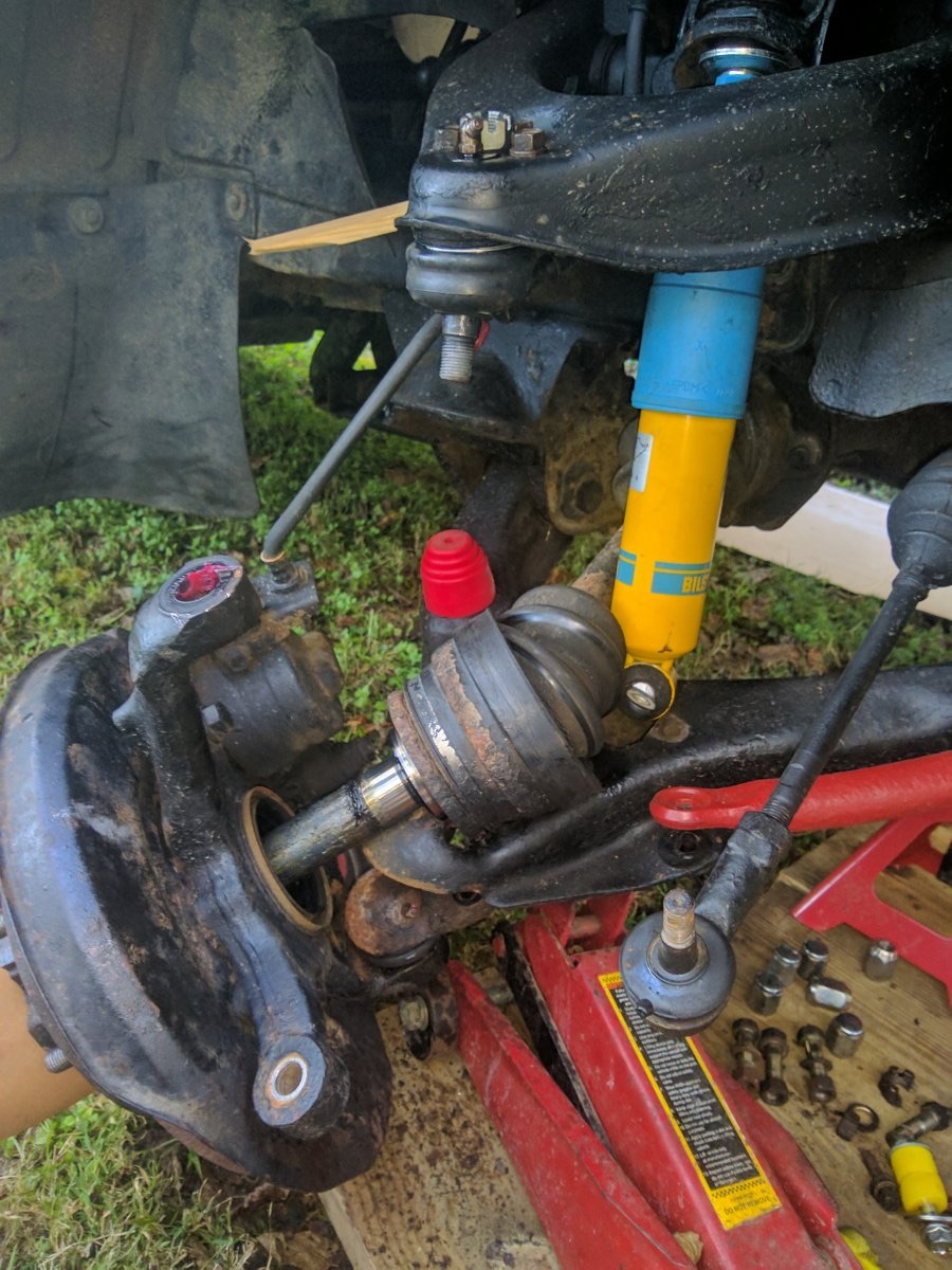 “Hang the heavy hub/knuckle/brake assembly from the framework above the shock to get the weight off of the brake lines, like this.” — Delica Forum, “Lower Ball Joint Questions.”
Separator tool
Rent a proper ball joint separator (AutoZone/Napa rent them free against a deposit) rather than buying a cheap one — multiple owners report Harbor Freight separators snapping mid-use. Avoid a fork-style (“taper fork”) separator if you plan to reuse any dust boots — it tears them; use a dedicated taper separator tool, or strike the solid steering knuckle (not the boot) with a heavy hammer right where the stud passes through to shock the taper free.
Pulling the whole lower arm
If you’re pulling the whole lower control arm for bushings, not just the ball joint: the front pivot bolt is a plain bolt, but the rear pivot bolt carries a large eccentric cam washer that sets your wheel alignment (camber/caster). Mark its exact position against the crossmember with a paint pen before loosening it, or you’ll throw your alignment out on reassembly.
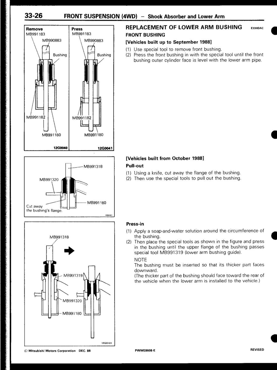 Factory service manual (PWWE8608), page 33-26 — bushing remove/press tooling, split by build date (pre/post Oct 1988).
Parts
OEM 4WD tie rod arm is MB351852; Pedders TE 715R is a commonly-used AU-available aftermarket cross-reference. See the full parts cross-reference for ball joint part numbers — flagged there as unverified between sources, don’t order against it blind.
Doing both joints at once — the technique that actually works
If you’re pulling both the upper and lower ball joint on the same side (which the community consensus below suggests you should — see “while you’re in there”), here’s the sequence that gets the knuckle off without a fight, synthesized from multiple owners who tried the “just the lower joint” approach first and gave up:
Sequence
- Disconnect the tie rod end first. Loosen the castle nut a couple of turns, flip it upside-down so it sits flush with the top of the tapered stud (protects the threads), then tap the taper loose with a separator or hammer through the nut.
- Disconnect the upper ball joint. Castle nut off, separator on, pop the taper. With the tie rod already free, the knuckle has room to move.
- Pull the axle circlip from inside the hub, behind the dust cover — support it, it can fly out under spring tension.
- Jack the lower control arm down slightly with the sway bar already disconnected (see above). This drops the knuckle down and forward, and — because the upper joint is already free — the axle comes out of the hub and the knuckle comes off the lower ball joint in one motion, rather than you fighting the lower taper separately.
- Only then deal with the lower ball joint’s four mounting bolts, with the knuckle already clear of the vehicle.
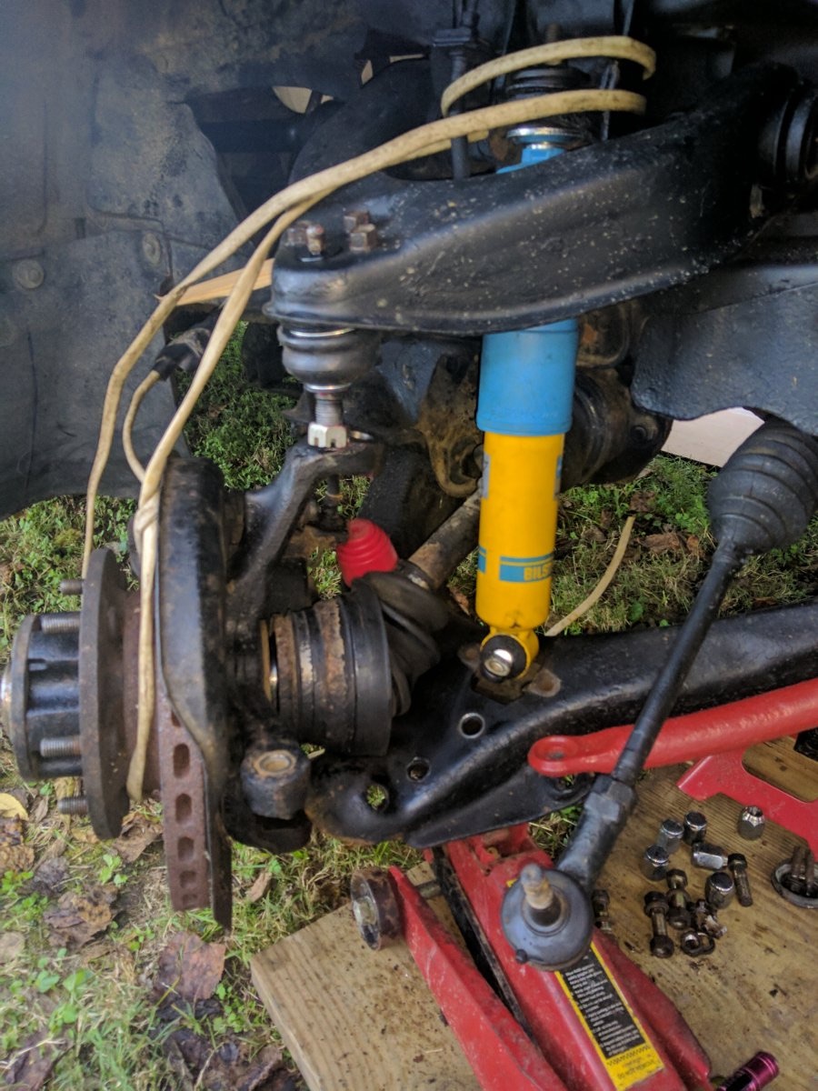 “I did same process as above to get mine out, i ended up undoing whole hub assembly and sway bar links to get enough movement to slide it out. Have the wire/rope available and at hand BEFORE you do all of this.” — ericpmasters, Oct 19, 2020, Delica Forum.
Separator technique
A fork-style tool tears boots and several owners report it simply not grabbing on these tapers. With a screw-type separator, leave the castle nut threaded on loose (not removed) before you wind the separator down — the separator presses against the nut rather than the exposed taper thread, which grips better and protects the thread if you’re reusing the stud. Position the separator at the angle shown in the manual’s own diagram; owners report other angles let the tool slip off under load rather than pop the joint.
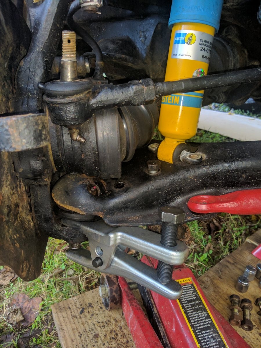 “Notice the angle of the separator. Any other angle wouldn’t allow the tool to grab, and it would pop off as I tightened it. … Notice how taut the brake hose is from the weight of everything. Don’t let it stay like that.” — Delica Forum, “Lower Ball Joint Questions.”
If it still won’t come apart
Some owners report success hammering the solid steering knuckle (never the boot) directly where the stud passes through, with the castle nut left on flush to protect the thread — a 4 lb dead-blow hammer, two solid hits, worked for one owner once there was enough swing clearance (pull the knuckle off the van first if you’re working close to the ground on jack stands — you need room for a full swing).
Alternative: pulling the whole front axle instead of fighting the joint in place
The ball joint thread itself links to a separate thread as “an easier way” for anyone finding the in-place approach too much of a fight. This is a bigger job than a ball joint swap — it involves the driveshaft, CV joints, and (in the source case) draining the differential — so treat it as a different scope decision, not a drop-in replacement for the steps above. Worth knowing about specifically because it preserves wheel alignment, where working the knuckle/subframe in place can disturb it.
Left-side procedure
Mirror for right.
- Turn the steering fully left, then remove the left sway bar end link (14 mm).
- Turn the steering fully right, then wedge wood between the upper wishbone and the upper bump stop — same torsion bar safety principle as the wood-block trick above.
- Loosen the left front wheel nuts before jacking.
- Jack the van up, onto axle stands, and pull the undertrays (12 mm and 14 mm sockets).
- Drain the differential oil (24 mm socket) — only needed if you’re going this far into the driveline.
- Remove the front wheel.
- Remove the caliper’s sliding bolts (17 mm) and tie the caliper up out of the way, same brake-hose caution as everywhere else in this job.
- Loosen (don’t fully remove) the left-side only 17 mm nuts on the rear subframe/crossmember.
- Split the steering knuckle with a ball joint separator or hammer.
- Remove the four 17 mm bolts holding the lower ball joint — these can be awkward to reach next to the CV joint.
- Undo the auto hub cover with a chain wrench.
- Remove the blind circlip inside (blind circlip pliers — you’ll need to dig grease out to find it) and the small shim behind it.
- Undo the three bolts holding the top swivel joint to the upper wishbone.
- Push the lower wishbone down and let the upper swivel joint fall forward.
- Pull the driveshaft straight out — angling it risks the diff housing’s oil seal. Wedge a tool between the CV joint and axle housing to release the spring clip holding it in. Don’t pull hard on the driveshaft itself — it’s possible to pull the CV joint apart.
- Mark the driveshaft’s orientation before it’s fully out.
- Mark the right-side CV joint, remove its nuts (bolts can stay in place), then the front mount bolt (17 mm), the four end-mount bolts (14 mm), and the two bracket-over-differential bolts (14 mm — reported as “a complete pain” to reach).
- The axle assembly drops out. It’s heavy — don’t be underneath it when it lets go. It may need a sideways slide to clear the CV joints if it’s hanging up.
Reassembly
Reverses the steps above, with (per the source) “more swearing as you try to lift the heavy axle” back into place.
Source
Delica Forum, “Removing the front axle — an easier way” (Growlerbearnz), done in the context of fitting a Lokka front differential locker — so the differential was already being opened up for other reasons. If you’re only after the ball joints, factor in that this route touches the diff and driveshaft too, which the in-place method doesn’t.
Is the ball joint actually worn, or is something else clunking?
Worth reading before you commit to pulling anything: a removed ball joint that’s genuinely bad won’t have play by hand, but it will make a knock or clunk when you push the stud through its full range of motion — even joints that “pass” the classic wheel-shake test and get signed off by two independent mechanics and a tyre shop have turned out to be the actual cause of a chassis clunk once pulled and bench-tested. If you’re chasing an intermittent clunk over bumps and everyone keeps telling you the joints are fine, that’s not necessarily the final word — mechanics test for gross play, not for the kind of internal knock that only shows up moving the joint through its arc by hand once it’s off the car.
Other causes to rule out
Before you conclude it’s the ball joint, also rule out: sway bar end link bushings and the bar’s hanger-bracket bushings (wear here causes a very similar clunk over almost any bump as the bar flexes), and subframe/crossmember bolts backed off slightly — a full re-torque pass with a torque wrench has been reported to measurably quieten a clunk on its own.
Attribution
The field notes and technique details above are synthesized from the Delica Forum thread “Lower Ball Joint Questions” (started by Sputnik, Oct 2020 — ongoing, confirmed no new replies beyond the sway-bar-clearance exchange as of this writing), contributions from forum users Sputnik, Growlerbearnz, InstrumentOfPeace, sealica, DustAngel, ericpmasters, and tlipoma, cross-checked against a related thread on pulling the front axle assembly as a whole (“Removing the front axle — an easier way,” Growlerbearnz). Not reproduced verbatim — see the archived PDF in Resources for the source thread.
Video references
Linked, not transcribed — descriptions aren’t accessible to fetch, titles confirmed: Mitsubishi Delica Upper Ball Joint Replacement (the torsion-bar warning above is timestamped from this one), and for a similar separator technique on a different vehicle, DIY Chevy Blazer Lower and Upper Ball Joint Replacement — Part 2.
Parts gotcha
Some replacement lower ball joints are pre-greased with no grease fitting; others have one, and the arm is handed left/right — the fitting hole faces the front of the vehicle. If you get the wrong side, pre-grease it by hand and plug the fitting hole with a 6 mm bolt rather than fighting a misaligned zerk.
Worth knowing
A worn lower ball joint can cause an intermittent clunk over bumps even when the joint passes a hand-play test and multiple mechanics sign it off as fine. One owner had two independent mechanics and a tyre shop all call the joints good; pulling them anyway and replacing found and fixed the clunk. Don’t take “no play by hand” as the final word if the symptom keeps coming back.
Source: Delica Forum, “Lower Ball Joint Questions,” started by Sputnik, Oct 2020 — synthesized from the thread’s accumulated fixes (Growlerbearnz, InstrumentOfPeace, sealica, tlipoma, and others), not reproduced verbatim. Full thread archived at /references/lower-ball-joint-questions-forum-thread.pdf on this site.
Torque specifications — 4WD
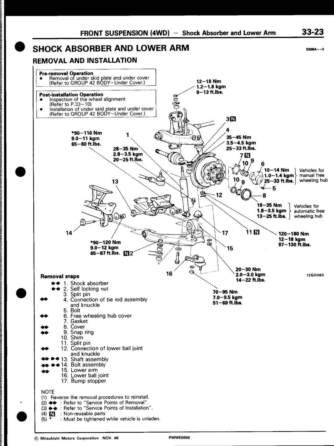 Factory service manual (PWWE8608), page 33-23 — the source diagram for the torque table below.
⚠️ Two sources disagree here, flagged rather than silently resolved. The table below is transcribed directly from the Mitsubishi factory service manual (PWWE8608) — treat it as primary since it’s the OEM source for OEM-spec joints. A secondary source (rockfordcv.com’s Mitsubishi torque page) gives noticeably lower values for the ball-joint-to-knuckle connections specifically: upper ball joint castle nut 43–65 ft·lbs (58–88 Nm) and lower ball joint castle nut 87–130 ft·lbs (118–177 Nm) — the lower figure happens to match the factory spec, but the upper figure is roughly half the factory value. rockfordcv.com is unreachable as of this writing (connection refused), so this can’t be independently re-verified against the live source right now — it’s carried over from a prior note. If you’re running aftermarket joints (e.g. Roadsafe), check the spec sheet that ships with them; aftermarket parts can legitimately call for different torque than OEM due to different metallurgy. Don’t average the two numbers or guess — confirm which spec applies to the part in your hand before torquing a steering-critical fastener.
| Fastener | Nm | ft·lbs |
|---|---|---|
| Lower ball joint to knuckle arm | 120–180 | 87–130 |
| Lower ball joint to lower arm | 70–95 | 51–69 |
| Upper ball joint to knuckle arm | 120–180 | 87–130 |
| Upper ball joint to upper arm | 35–55 | 25–40 |
| Lower arm to gear mounting crossmember | 90–120 | 65–87 |
| Lower arm to suspension crossmember | 90–110 | 65–80 |
| Upper arm to frame | 120–160 | 87–116 |
| Tie rod assembly to knuckle arm | 35–45 | 25–33 |
| Front damper bracket to frame | 60–70 | 43–51 |
| Torsion bar adjusting nut to torsion bar locking nut | 40–50 | 29–36 |
| Stabilizer attaching bolt to hanger | 9–14 | 7–10 |
Lubricant & sealant
Lubricant: multipurpose grease (SAE J310, NLGI No. 2) — for both ball joints, the torsion bar serrations, dust covers, and the torsion bar anchor bolt.
Sealant: 3M ATD part No. 8663 or 8661 (or equivalent) on the slot of the upper ball joint.
Lower ball joint — via lower arm removal
The lower ball joint comes out as part of the lower arm assembly.
- Remove the under skid plate and under cover.
- Remove the shock absorber.
- Remove the self-locking nut (non-reusable — always fit a new one on reinstall) and split pin.
- Disconnect the tie rod assembly from the knuckle. Loosen the slotted nut 2–3 turns (don’t remove it fully), then use the steering linkage puller (MB990635 or MB991113) to break the tie rod ball joint free. Tie the puller’s safety rope to the lower arm so it can’t slip off when the joint lets go.
- Remove the bolt.
- Free wheeling hub cover — manual hub: set the control handle to FREE and remove the cover. Automatic hub: shift the transfer to 2H and reverse 1–2 m to put the hub in the free condition, then remove the cover (use an oil filter wrench with a cloth if it won’t loosen by hand — don’t damage the cover).
- Remove the gasket.
- Remove the cover.
- Remove the snap ring from the drive shaft using the snap ring tool (MB990628).
- Remove the shim.
- Remove the split pin.
- Disconnect the lower ball joint from the knuckle. Same technique as the tie rod: loosen the slotted nut 2–3 turns, then use MB990809 to break the joint free.
- Remove the shaft assembly — mark it against the crossmember first so reassembly lines up.
- Remove the bolt assembly — same match-marking.
- Remove the lower arm. Raise the hub and knuckle assembly to clear the lower arm from the knuckle. Be careful not to damage the drive shaft dust cover or the ball joint dust cover on the way out.
- The lower ball joint comes off with the arm (integral — not a separate removal step).
- Remove the bump stopper.
Reverse the steps to reinstall, torquing each fastener to the values above. Align the match marks you made on the shaft/bolt assembly and crossmember before final torque.
Lower ball joint checks
Axial backlash: fit a dial gauge and measure axial movement at the joint. Limit is 0.5 mm. Replace the ball joint (i.e. the lower arm) if backlash exceeds that, or if the joint doesn’t move under light finger pressure even within limit.
Dust cover replacement (if the boot has torn but the joint itself checks out): pack the interior of the new dust cover and the joint with multipurpose grease, then secure the cover to the joint with its retaining ring.
Upper ball joint — via upper arm removal
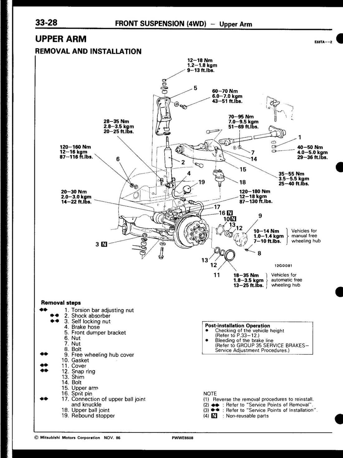 Factory service manual (PWWE8608), page 33-28.
- Remove the torsion bar adjusting nut — measure the anchor bolt’s exposed length first and record it as your reinstall reference.
- Remove the shock absorber.
- Remove the self-locking nut (non-reusable).
- Disconnect the brake hose.
- Remove the front damper bracket. 6–8. Remove the associated nuts and bolt.
- Free wheeling hub cover — same manual/automatic procedure as the lower arm job above.
- Remove the gasket.
- Remove the cover.
- Remove the snap ring from the drive shaft (MB990628).
- Remove the shim.
- Remove the bolt.
- Remove the upper arm.
- Remove the split pin.
- Disconnect the upper ball joint from the knuckle. Loosen the slotted nut 2–3 turns. Pull the lower arm down slightly (not further than necessary — you can damage things by overextending it) and set the special tool (MB990809), then break the joint free.
- The upper ball joint comes off the arm (riveted — arm and joint are replaced together).
- Remove the rebound stopper.
Reverse to reinstall. Post-installation: check vehicle height, then bleed the brake line (you disconnected the brake hose in step 4).
Upper ball joint checks
Starting torque: after fitting the nut to the joint, shake the stud 4–5 times, then measure the starting torque with the preload socket (MB990326) and a torque wrench. Standard value: 0.8–3.5 Nm (7–30 in·lbs). Out of spec → replace the upper arm. Under spec is still usable unless there’s play or roughness in the joint’s movement.
Dust cover replacement: grease the interior of the cover and the joint, apply the specified sealant (3M ATD 8663/8661) to the grooves on the joint, then secure the cover with its ring.
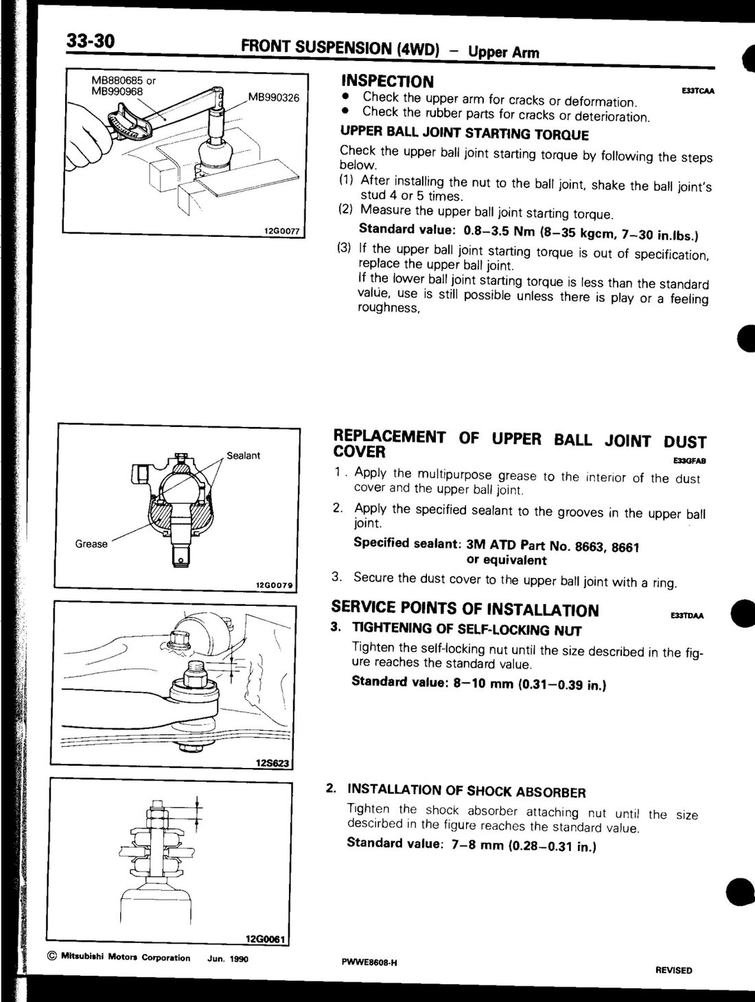 Factory service manual (PWWE8608), page 33-30 — starting torque check and dust cover sealant/grease diagram.
FAQ
Can I just buy a replacement ball joint for my Delica?
No — not for the front suspension. Both the upper and lower ball joints are part of their respective control arm assembly, not separately sold/pressed-in components. You’re buying (or rebuilding) the whole arm.
Is this the same procedure for a 2WD Star Wagon?
No. The 2WD front suspension uses different arms, and the manual’s 2WD lower/upper arm removal steps are a separate section (manual pages 33-15 to 33-17 in the same combined PDF). Torque values for the ball joint fasteners are identical between 2WD and 4WD; the arm removal steps differ because of the extra driveshaft/hub hardware on 4WD.
What torque should I run on the lower ball joint to knuckle?
120–180 Nm (87–130 ft·lbs), same for both upper and lower joint-to-knuckle connections.
Converted from the Mitsubishi factory service manual (document PWWE8608), Group 33 — Front Suspension, 4WD section, printed pages 33-23 to 33-30. Torque table values shown are the Jun. 1994 revision; earlier-build vehicles should cross-check against the original 1986/1988 values in the same manual if working on pre-1994 hardware.
Last updated 2026-09-23.