Rear Drum Brake Shoe Replacement (4WD)
Replacing the rear drum brake shoes on a 4WD L300 / Delica Star Wagon (leading-and-trailing type), converted from the factory service manual — torque specs, wear limits, and the full removal procedure.
- Manual section
- Group 35 — Service Brakes
- Manual pages
- 35-79 to 35-84 (4WD, leading-and-trailing)
- Applies to
- L300 / Delica Star Wagon, 4WD — leading-and-trailing drum type. 2WD uses a different (duo-servo) drum brake — see note below.
Tools needed
M8 x 1.25 bolt
threads into the drum flange to help pull a stuck drum
MB990806
brake spring remover/installer (for the wheel cylinder return springs, if replacing the cylinder)
Which drum type do you have?
The manual splits this job into two different procedures: duo-servo (most 2WD) and leading-and-trailing (4WD). They use different spring/lever hardware and different wheel cylinder torque specs. This guide covers the 4WD leading-and-trailing procedure. If you’re working on a 2WD Star Wagon, confirm your drum type before following these steps — don’t assume.
Torque specifications
| Fastener | Nm | ft·lbs |
|---|---|---|
| Wheel cylinder to backing plate (rear, duo-servo type) | 8–12 | 6–9 |
| Wheel cylinder to backing plate (rear, leading-and-trailing type) | 18–21 | 13–15 |
| Bleeder screw | 7–9 | 5.2–6.6 |
Lubricant: Brake grease (SAE J310, NLGI No. 1) — shoe/lever and shoe-and-lining contact points on the backing plate, anchor plate and wheel cylinder piston edges, and the adjuster lever assembly.
Sealant: 3M ATD Part No. 8513 (or equivalent) — shoe hold-down pin at the backing plate, and the wheel cylinder-to-backing-plate contact surface if you’re pulling the cylinder.
Removal steps
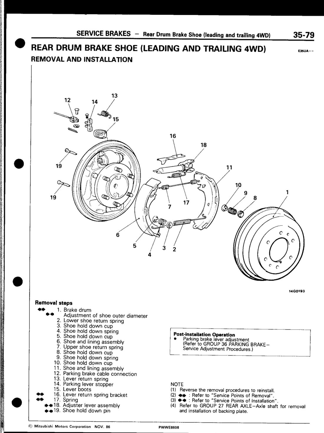 Factory service manual (PWWE8608), page 35-79.
- Remove the brake drum. If it’s stuck, thread an M8 × 1.25 bolt into the hole on the drum flange and turn it in to push the drum off.
- Remove the lower shoe return spring.
- Remove the shoe hold-down cup, spring, and cup (lower shoe).
- Remove the shoe and lining assembly (lower).
- Remove the upper shoe return spring.
- Remove the shoe hold-down cup, spring, and cup (upper shoe).
- Remove the shoe and lining assembly (upper).
- Disconnect the parking brake cable.
- Remove the lever return spring.
- Remove the parking lever stopper.
- Remove the lever boots.
- Remove the lever return spring bracket — pull it out with pliers along with its spring.
- Remove the spring.
- Remove the adjuster lever assembly.
- Remove the shoe hold-down pin.
Reverse to reinstall. Adjust shoe outer diameter (see below) before final drum fit, and do the parking brake lever adjustment as a post-install step (Group 36).
Inspection
- Lining wear: measure lining thickness at the most worn point. Limit is 1.0 mm. Replace the shoe and lining assembly if worn past that, or if wear is badly uneven side to side. Replace both sides together, even if only one is worn.
- Drum bore: measure at more than two locations. Limit is 256.0 mm. Replace the drum if it’s worn past that or badly out of round.
- Lining-to-drum contact: chalk the inside of the drum, rub it against the shoe and lining, then check the contact pattern. Replace the shoe/lining or the drum if the contact area is very irregular. Clean the chalk off afterward.
Adjusting shoe outer diameter
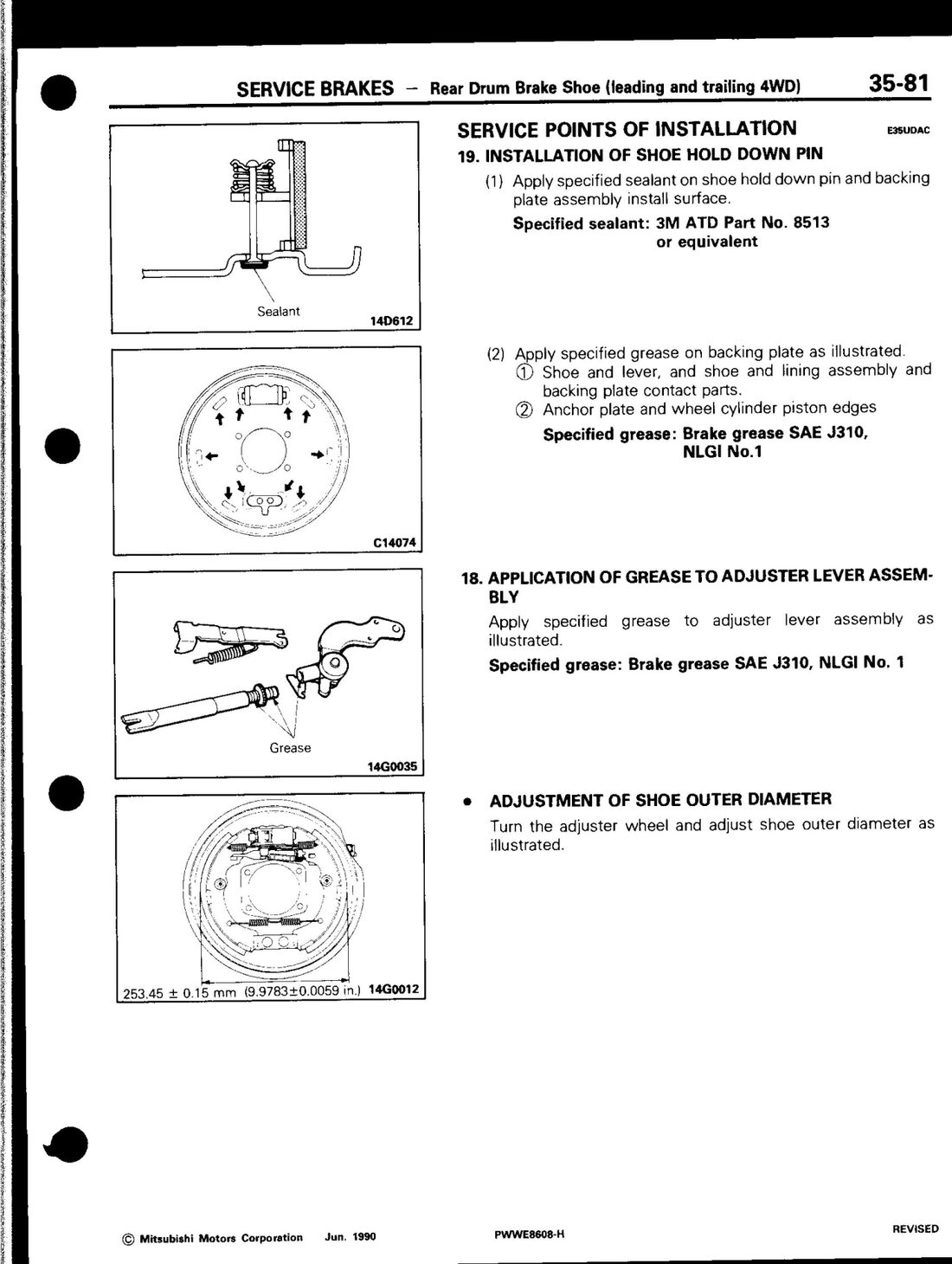 Factory service manual (PWWE8608), page 35-81.
Turn the adjuster wheel to bring the shoe outer diameter to 253.45 ± 0.15 mm.
If you’re also replacing the wheel cylinder
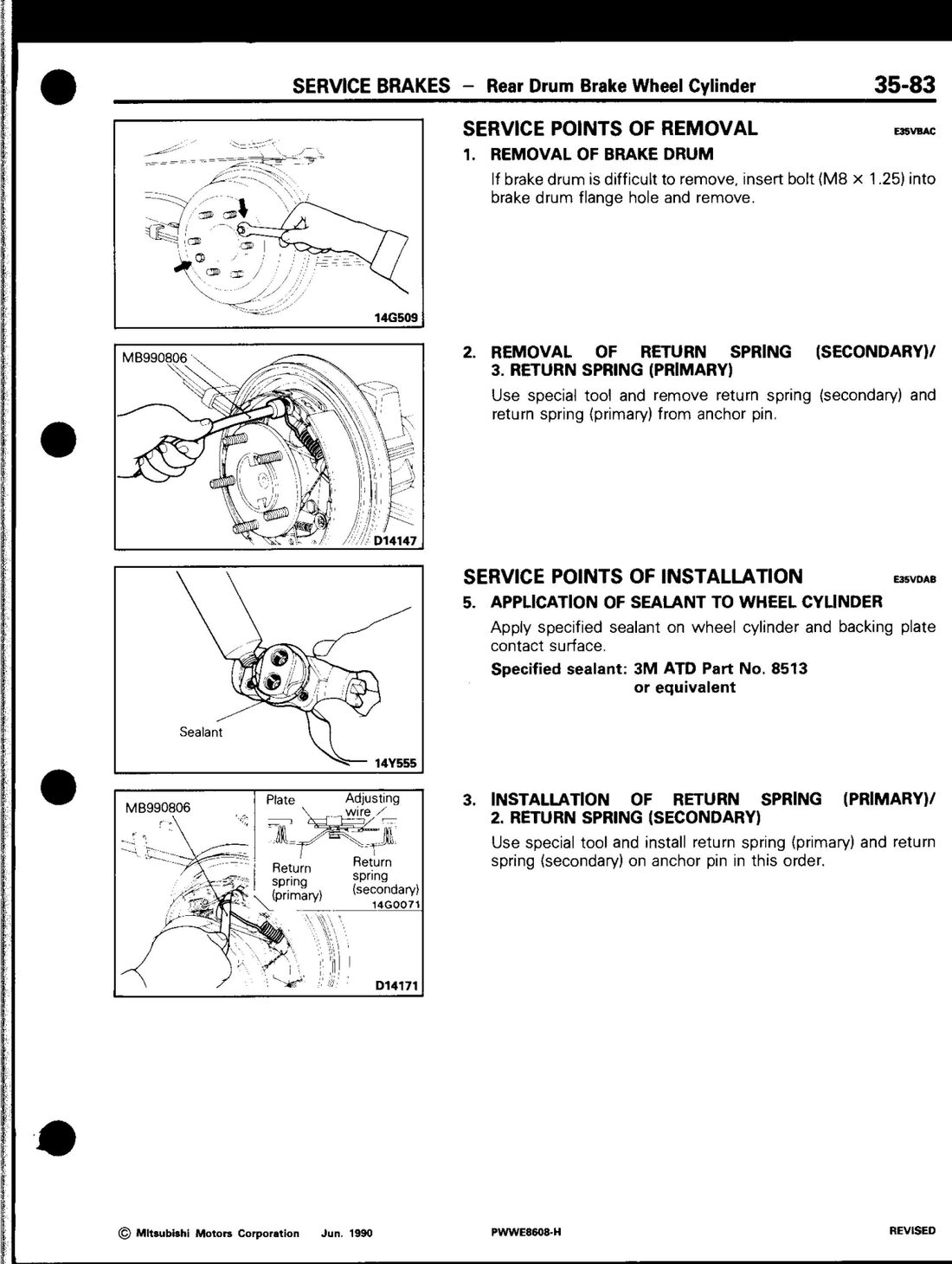 Factory service manual (PWWE8608), page 35-83.
- Drain the brake fluid first (pre-removal).
- Remove the brake drum (same M8 bolt trick if stuck).
- Remove the secondary return spring, then the primary return spring, from the anchor pin — use the spring remover tool (MB990806) rather than fighting it by hand.
- Disconnect the brake tube.
- Remove the wheel cylinder.
Reinstall in reverse, applying sealant to the wheel cylinder/backing plate contact face, then refit the return springs primary first, then secondary, back onto the anchor pin. Torque to 18–21 Nm (leading-and-trailing type — see table above, don’t use the duo-servo figure). Finish with a brake fluid fill and full line bleed.
Converted from the Mitsubishi factory service manual (document PWWE8608), Group 35 — Service Brakes, printed pages 35-79 to 35-84 (4WD leading-and-trailing) and 35-8/35-9 (torque and lubricant specs).
Last updated 2026-09-23.